The Opposite of Blink
On the third page, we explored an output using a blinking LED. In this exercise, we’ll explore the input abilities of the Arduino platform using a simple sensor, a photocell. We’ll also explore how we can use our connected computer to view the sensor readings.
First, let’s explore how a sensor works. At its simplest, each sensor contains chemicals that affect the circuit through resistance. These chemicals respond to stimuli specifically to the phenomena we want to explore; for photoresistance, the resister responds to photons. Here’s the resistance versus illuminance of the photoresistor, taken from the technical documentation:
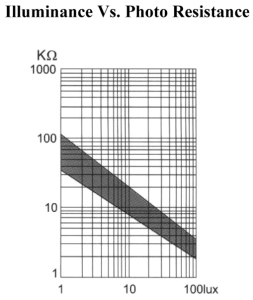
We can see that the more illumination–-the increase in lux–leads to decreased resistance along a linear trend. This relationship allows us to estimate the amount of illumination in a space. It is worth noting that we can only measure relative illuminance versus exact illuminance due to the type of photoresistor we are using.
Let’s explore this on our platform.
Circuit Diagram and Code
You’ll need the following from your hardware kit:
- Photocell (power: 5v, analog pin 3)
- 10k ohm resister
- breadboard
- 3 x cables
void setup() {
  // Serial communication at 9600 bps.
  Serial.begin(9600);
  Serial.println("Starting Photocell.");
}

void loop() {
  // reads the input on analog pin A3 (value between 0 and 1023)
  int analogValue = analogRead(A3);

  Serial.print("Analog reading: ");
  Serial.print(analogValue);   // the raw analog reading

  // Creating four relative and course classifications
  if (analogValue < 10) {
    Serial.println(" - Dark");
  } else if (analogValue < 300) {
    Serial.println(" - Dim");
  } else if (analogValue < 600) {
    Serial.println(" - Bright");
  } else {
    Serial.println(" - Very bright");
  }

  delay(500);
}
The output should display a categorical description of illuminance: dark, dim, bright, and very bright. The measurements are taken every half a second.